BES Electronic Systyems

Home       Products & Services     Contact us       CMC-e- 600 ICD        CMC-e-600 data sheet       

CMC-e-600 SOFTWARE BY AMPOL


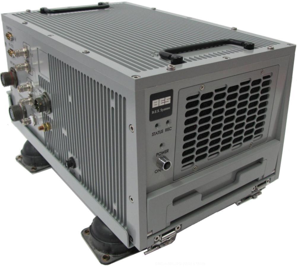
Built for the CAAS system on the CH-47F, MH-47G and MH-60L/M , the dataMARS CMC-e-600  is an exceptional solution for flight-data recording and analysis, completely integrating an airborne recording unit with powerful ground analysis software.

The CMC-e-600 made from the Flight Worthy CMC-e rugged PC with the dataMARS software. The recorder includes a Removable Memory Module (RMM) of 0.5 Terabyte that stores the collected flight data. During flight the unit monitors and records the entire traffic, (or selected portions) of two MIL-STD-1553 buses and the entire traffic (NDO level) of two Ethernet channels. Before and during the flight the unit is capable to display monitored engineering-unit data, enabling quick and informed decision-making during and between flights. Recorded data is time tagged with reference to IRIG-B time code or internal PC clock. Once on the ground, the RMM  pocket-sized, media cartridge can be easily removed and taken to the lab, where the powerful Windows-based dataMARS post-analysis software immediately accesses and analyzes the data, with no downloading required. The dataMARS post-analysis software provides advanced data presentation, manipulation, interrogation, reporting and exporting capabilities.

Reliable and rugged, the The CMC-e-600 is SOF (Safety of Flight) tested, flight qualified and can withstand severe environmental conditions. Compact and easy to install, the unit is self-cooled and operates autonomously from a 12-36VDC  power source.

dataMars on CMC-e-600 Platform


CMC-e- 600 Specifications


Graphic User Interface. Click to enlarge

Recording Media:

Industry standard SATA 2½” disk, fully PC-compatible

Various capacity options, 

Data Sources

Up to 4 dual-redundant MIL-STD-1553 buses (Special option to operate as BC/RT)

6 ARINC-429 channels (12.5kHz, 100kHz)

2 10/100baseT Ethernet connections

IRIG-B or internal time tagging on all recorded data. Option for GPS 1PPS sync

Power

80Watt @ 12-36VDC (typical), up to 80 Watts depending on configuration

Dimensions & Weight  

230x245x370 [mm] (WxHxL)  with base and mounts 

Weight approx.12Kg with mount and shock isolators  


Environmental


Operating Temperature: 0°C - 55°C   

Non-operating Temperature: -20°C - 85°C

Relative humidity: Up to 95% relative humidity,

                           non-condensing, MIL-STD-810F

Salt Fog: 5% solution per MIL-STD-810F method 509.3

Vibrations: MIL-STD-810F 

Shock: MIL-STD-810F for flight equipment 15g, 11ms saw tooth 

Altitude: 15,500ft (or the equivalent atmospheric pressure) operating and non-operating with hard disk,  15,00ft  40.000ft non- operating

EMI/RFI: MIL-STD-461C Categories CE03, RE02, RS03, CS02

Fungus: MIL-STD-810F

Sand and Dust: per MIL-STD-810F

Message Structure Database


Message Structure Database. Click to EnlargeThe dataMARS and dataSIMS products use an ICD database to enable extraction of engineering-unit data from monitored and replayed communication messages. This database describes the data format of individual types of messages, as well as the engineering-unit elements they contain. The mapping and encoding details of these elements are then used to decode their engineering-unit values during monitoring and replay. These values are displayed in graphical and numerical displays, and are also presented in the different report types supported by the software. Engineering-unit element settings also enable detection of illegal (alarm) element values and mapping of values to text. When simulating engineering-unit data via dataSIMS, the ICD encodes the data into a transmitted raw message 


Data Display


Data Display. Click to EnlargeThe dataMARS and dataSIMS visualize recorded and replayed data using a wide variety of graphical and alphanumeric displays. They offer display formats that show engineering-unit values in plots, needles, bars and numbers, as well as display formats that show the complete messages and sequences of messages. You can create display setups that include multiple display pages with hundreds of displays for elements, messages and streams, without losing speed and efficiency.


Virtual Panels


Virtual Panels. Click to EnlargeVirtual Panels are a major add-on package option that simplifies access to monitored and simulated data by constructing realistic looking front panels from an extensive library of gadgets. You can use these panels to control a real piece of equipment, as well as simulate or create virtual equipment that can communicate on a live bus. Virtual Panels can also be useful in emulating and testing a proposed front panel design, in order to simplify the user interface for data monitoring. Virtual panels may be extended to include new types of displays and ActiveX controls. A provided SDK allows the creation of custom controls.

Virtual Panels are useful in mimicking the look, feel and operation of real equipment used by the pilot by presenting the recorded data via "real-life" controls. The intuitive interface is especially helpful for users who are not familiar with the dataMARS and dataSIMS systems.

Post-analysis Capabilities


Post-analysis Capabilities. Click to EnlargeThe dataMARS and dataSIMS offer superb post-analysis capabilities for recorded data. Supported recordings include those created by dataMARS, dataSIMS and the dataMARS104-II systems. Recordings made by recorders from other vendors may also be imported for analysis.

Post-analysis is performed on engineering-unit values decoded from the recorded data, which are displayed using a variety of presentation formats, and reported in flexible reporting formats. Specific events and conditions can be searched for in the recorded data, and calculations may be performed on it to extract new information to be displayed and reported alongside the recorded data. Recorded data may be exported to other third-party tools, such as Excel™ and MatLab™.

Data from multiple sources are replayed synchronously, based on recorded time tags. The data may be replayed at various rates, such as 1:1 and full speed.

Aside from the engineering displays that show recorded


Data Reporting and Exporting

Data Reporting and Exporting. Click to EnlargeA variety of ASCII reports can be generated from the recorded data. These include engineering-unit values, results of additional calculations based on monitored data and the raw data of complete messages. Reports may be generated for either complete recordings or for selected portions of them. Report templates may be used to generate multiple reports for numerous data recordings in a single batch process.

Use other optional conversion tools to convert recorded data to various third party binary formats.

Reported data may be used in Excel™, MatLab™ and other tools for dedicated analysis and presentation. Reports may also be distributed to other interested parties


Custom Data

Custom Data. Click to EnlargeThe dataMARS and dataSIMS make it possible to incorporate and integrate custom data communications channels into the system in order to utilize its monitoring, display, storage, post-analysis and database capabilities. They provide you with a driver (with full source code) that you can easily modify to receive and transmit custom data. This driver may be used for the monitoring of custom hardware, custom RS232/422 protocols, GPS data, analog I/O and more.

Custom data are monitored and simulated alongside standard protocols (for example, MIL-STD-1553 or ARINC-429), which re-emphasizes the complete and system-wide approach taken by the dataMARS and dataSIMS


MIL-STD-1553MIL-STD-1553. Click to Enlarge

Monitors all or selected bus traffic, and detects communication errors.

Decodes engineering-units data from monitored MIL-STD-1553 messages.


ARINC-429


ARINC-429. Click to Enlarge

Monitors multiple high- and low-speed ARINC-429 channels, and detects communication errors.

Decodes engineering-unit data from monitored ARINC-429 labels.

Uses a comprehensive built-in database of standard ARINC-429 labels, as well as provides support for user-defined label formats.  

Ethernet

Ethernet. Click to Enlarge

Monitors TCP, UDP and IP transmissions either passively or as an active node.
Identifies packets and frames by source/destination address and port.
Decodes engineering-units data from monitored transmissions at any protocol layer
Tracks sockets and decodes stream data.
Easily customized to support custom network protocols (based on IP, UDP or TCP).

Copyright © 2010. 

BES Systems Ltd. 14 Moshe Levi St. Rishon Unit 30  Israel, CAGE SK477

 Tel: +972-3-5714998   Fax:+972-3-571-5085    email: asherlav@bes.co.il